- All
- Product Name
- Product Keyword
- Product Model
- Product Summary
- Product Description
- Multi Field Search
Views: 0 Author: Site Editor Publish Time: 2026-08-17 Origin: Site
ESR affects resonance capacitor losses and temperature rise by converting RMS current into heat. The basic relationship is P = I² × ESR, which means capacitor loss increases with both ESR and the square of RMS current. For high-frequency resonant circuits, ESR should therefore be evaluated together with operating frequency, current waveform, voltage stress, thermal path, and mounting conditions.
ESR is the real resistive portion of a capacitor’s impedance. It converts RMS current into heat: ESR loss = RMS current² × ESR.
In a resonant tank circuit, circulating current can be much higher than input current, so a small ESR difference can produce a meaningful change in capacitor losses.
ESR is frequency-, temperature-, construction-, and connection-dependent. A value measured under one condition is not automatically suitable for another.
Temperature rise depends on both internally generated loss and the ability of the installed capacitor to release heat to its surroundings.
Selection should combine capacitance, voltage, RMS current, peak current, frequency, ESR or dissipation-factor data, derating, terminals, layout, and thermal validation.
An ideal capacitor would store and return energy without resistance. A physical part also contains resistance in its electrodes, terminations, internal connections, and dielectric-loss mechanisms. Engineers represent the combined loss with an equivalent series resistance (ESR) placed in series with the ideal capacitance. This compact model is useful because the resistive portion is where electrical energy becomes heat.
For a capacitor carrying sinusoidal or non-sinusoidal AC current, a first-order estimate of capacitor ESR losses is: ESR loss = RMS current² × ESR.
The equation is simple, but it carries an important design message: current is squared. If RMS current doubles, the ESR-related loss increases by four times when ESR is unchanged. In high-frequency power electronics, that is often more consequential than a small difference in nominal capacitance.
The full impedance of a real capacitor also includes capacitance and equivalent series inductance (ESL). In plain-text form, it can be expressed as: Impedance = ESR + j × (ωL − 1/(ωC)).
At the capacitor’s own self-resonant frequency, the inductive and capacitive reactances cancel and the remaining impedance is predominantly resistive. In an application, however, the relevant question is broader: what are ESR, current, voltage, and temperature at the operating frequency and waveform? A catalog ESR value at a reference frequency should therefore be treated as a datum for comparison, not as a universal loss prediction.
ESR converts part of the electrical energy flowing through the capacitor into heat. When RMS current increases, the effect becomes more significant because current is squared in the loss equation.
For example, if RMS current increases from 12 A to 18 A while ESR remains 8 mΩ, the estimated ESR loss increases from approximately 1.15 W to 2.59 W.
This is why engineers should not select a resonance capacitor based only on nominal capacitance and voltage. RMS current, operating frequency, ESR, thermal path, and installation conditions must also be evaluated.
ESR heating starts inside the component. The generated power must then travel through the winding, dielectric, resin or case, terminals, surrounding air, mounting structure, and any intentional cooling arrangement. A useful thermal approximation is: Temperature rise ≈ Power loss × thermal resistance.
Here, thermal resistance describes the effective path from the capacitor’s heat-generating region to ambient. This is not a substitute for qualification testing, because real thermal paths are affected by orientation, clearance, airflow, conductor size, nearby hot parts, enclosure design, and duty cycle. It does show why lowering loss and improving cooling are complementary rather than interchangeable actions.
ESR is not the only contributor to loss. Dielectric loss, conductor loss, skin effect at elevated frequency, terminal resistance, and losses in external busbars or PCB traces may all affect the observed temperature. The capacitor’s dissipation factor is useful as a complementary indicator of loss, especially when it is specified at the reference frequency and temperature relevant to the design. Neither a low dissipation factor at 1 kHz nor a low ESR at another test condition removes the need to evaluate the actual operating point.
The following hypothetical calculation illustrates the squared-current effect. It is not a product rating or a temperature prediction; the actual permitted current and temperature rise must come from the applicable datasheet and system test.
Operating case | RMS current | Assumed ESR at operating condition | Estimated ESR loss |
|---|---|---|---|
Reference condition | 12 A | 8 mΩ | 1.15 W |
Same current, higher ESR | 12 A | 14 mΩ | 2.02 W |
Higher circulating current | 18 A | 8 mΩ | 2.59 W |
The comparison is useful because it separates two levers. With the same current, reducing ESR lowers internal heating in direct proportion. With the same ESR, a rise in RMS current has a squared effect. In practice, a design review should also include the ESR of terminals and interconnects, since heat generated outside the dielectric can still warm the capacitor and consume thermal margin.
Equivalent series resistance (ESR) is not a fixed material label. Its value can change with frequency, temperature, voltage, capacitance, package geometry, terminal configuration, and measurement method. A good procurement specification names the required operating frequency or frequency range rather than asking only for “low ESR.”
At lower frequencies, dielectric and conduction effects may dominate the loss profile. As frequency rises, electrode, termination, and skin-effect contributions become increasingly relevant. The position of the operating frequency relative to self-resonance also matters: above self-resonance, parasitic inductance changes the capacitor’s apparent behavior and may introduce unexpected loss or waveform stress.
Temperature dependence deserves the same caution. Different capacitor technologies and constructions can respond differently as they heat. The electrical properties of the film and electrodes may shift, while the surrounding system becomes less able to reject heat if ambient temperature increases. A thermal design should consider the highest realistic ambient condition, not only room-temperature bench measurements.
For high-current resonant duty, polypropylene film capacitors are commonly selected because film construction can offer low dielectric loss and stable behavior suited to demanding AC operation. Still, material choice alone is not enough. Electrode design, winding geometry, end-spray connections, lead or lug design, encapsulation, and the current path into the assembly all influence effective ESR and ESL. The best component is the one whose documented limits and construction fit the intended electrical and mechanical installation.
ESR describes loss within the capacitor model; it does not erase the resistance and inductance added by the rest of the loop. Long leads, narrow traces, undersized busbars, loose hardware, oxidized contact surfaces, and a remote capacitor location add impedance. At high frequency, a layout with unnecessary loop area can also increase inductive voltage overshoot and alter current sharing.
Treat the capacitor, connections, and switching loop as one electrical and thermal system. Keep the resonant-current path short and direct. Use terminal hardware and conductor sizes appropriate for the expected RMS and peak current. Avoid placing the capacitor beside heat-producing magnetics, semiconductors, or resistors without confirming the resulting ambient temperature. When several parts operate in parallel, symmetrical connections matter: unequal path resistance or inductance can push disproportionate current into one capacitor and invalidate a simple “total current divided by quantity” assumption.
This is particularly important in high-frequency power electronics, where a component that looks suitable in a standalone LCR measurement may experience different current distribution after it is mounted. Verify the final assembly with representative switching frequency, control mode, load variation, and cooling conditions.
The selection process starts with the resonant network, not the component catalog. Determine the required capacitance and tolerance, then calculate the voltage waveform, RMS current, peak current, frequency range, duty cycle, and expected transient conditions. Next, match those results to a capacitor family’s application data and request part-specific limits when the operating point is close to a boundary.
For a starting point, the resonant capacitor range is described for high-frequency resonant circuits using PP film dielectric and identifies low ESR and low-loss characteristics as core selection considerations. The range also covers applications where high voltage and current handling are relevant. Those facts support an application conversation, but they do not replace checking the data for the selected model, capacitance, voltage, temperature, and frequency.
Use the following decision framework during design review:
Checkpoint | What to verify | Why it matters |
Resonant operating range | Frequency at normal, minimum, and maximum operating conditions | ESR and impedance may change across the control range. |
Current waveform | RMS, peak, crest factor, and duty cycle | RMS current determines resistive heating; peak current and dv/dt can set additional limits. |
Voltage stress | Continuous AC/DC voltage, resonant magnification, surge, and margin | Nominal supply voltage may not equal capacitor terminal stress. |
Loss data | ESR and/or dissipation factor at stated test conditions | Prevents comparing values measured at unrelated frequencies or temperatures. |
Thermal path | Ambient, airflow, spacing, mounting, terminals, and adjacent heat sources | Determines whether internal loss becomes acceptable temperature rise. |
Interconnect design | Lead length, busbar or PCB resistance, symmetry, and contact quality | Limits external loss and current imbalance. |
Validation plan | Instrumented prototype test at worst credible conditions | Confirms model assumptions and reveals installation effects. |
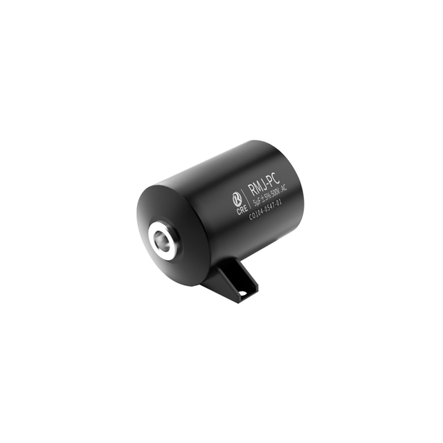
A documented example is the CRE RMJ-PC high-voltage resonance capacitor. Its published product information identifies applications in series/parallel resonant circuits and induction-heating resonance, and lists low ESR and ESL among its features. It also specifies that RMS-current capability is model-dependent and should be checked in the specification sheet. That is exactly the right level of discipline for a resonant design: use the category and product information to narrow the candidate, then verify the electrical and thermal limits of the exact part.
The relevant product advantage is not a vague claim that one capacitor is best for every resonant circuit. It is the combination of documented electrical characteristics, application fit, and construction choices that can reduce design risk when they match the actual resonant duty. The published CRE resonance/snubber capacitor information identifies a polypropylene-film dielectric, low ESR, low ESL, PCB-mountable construction, and suitability for high-frequency applications. These characteristics directly address the two parasitics that shape loss and waveform behavior in a compact resonant-current loop.
For a resonant capacitor, low ESR supports lower resistive loss at a given RMS current, while low ESL helps keep the capacitor and its connection path from adding unnecessary inductive behavior. The published range identifies both attributes rather than treating capacitance as the only parameter. That creates a better starting point for LLC stages, resonant charging, series/parallel resonant circuits, and related high-frequency power assemblies. The final result still depends on the selected value, terminals, and physical layout, but the product characteristics are aligned with the technical requirements discussed in this article.
The resonance/snubber product page lists a capacitance range of 0.00022–8 μF and a rated-voltage range of 250–2000 V for that product family, with stated use in LLC resonant circuits, switched-mode power supplies, series/parallel resonant circuits, and IGBT snubber duty. This breadth gives engineers a defined family to assess across several resonant and switching applications. It does not mean every listed part is interchangeable: the required capacitance, current, temperature range, voltage waveform, and mounting condition must still select the final model.
Where a higher-voltage resonant component is needed, the RMJ-PC product page documents a 1200–2000 VDC range, 1–8 μF capacitance range, copper-nut leads, resin-sealed plastic packaging, high-frequency current-carrying capability, and high pulse-current and dv/dt withstand capability. These are useful product advantages when the installed design requires a compact, mechanically practical connection and elevated electrical stress capability. They should be read with the accompanying limitation: the page directs designers to the specification sheet for model-specific RMS-current and pulse-current limits. That distinction helps prevent a product advantage from being mistaken for an unconditional system guarantee.
Laboratory validation should reproduce the electrical and thermal environment as closely as practical. Measure capacitor current with a method suited to the waveform and bandwidth, then record voltage, switching frequency, load, ambient temperature, and cooling configuration. If using an LCR meter to compare parts, record the test frequency, AC test level, fixture, and temperature; otherwise, a small measured difference may reflect the measurement setup rather than the component.
For thermal checks, distinguish case temperature from the internal hot spot. Case measurement is valuable for comparison and monitoring, but it may not directly equal the hottest internal region. Use the manufacturer’s stated temperature limits and, where available, its guidance on hot-spot or case-temperature interpretation. Allow enough time for the assembly to reach thermal equilibrium, and repeat the test at the combination of ambient temperature, input condition, frequency, and load that creates the worst credible stress.
Infrared imaging can quickly reveal a poor terminal contact, a hot busbar transition, or uneven sharing among parallel capacitors. Its readings require suitable surface emissivity and line-of-sight, so confirm suspicious results with contact sensors when needed. The goal is not merely to prove that a sample survives a short run; it is to establish repeatable thermal margin for manufacturing variation, blocked airflow, seasonal ambient changes, and realistic load cycles.
One common mistake is treating a capacitance and voltage match as a complete selection. In a resonant application, RMS current and frequency suitability can be equally decisive. Another is comparing ESR values without noting the reference frequency or temperature. A third is assuming that an external fan solves every problem; airflow may lower case temperature while a poor internal or terminal current path still creates local heating.
Designers also sometimes optimize the capacitor while overlooking the resonant loop. A low-loss device connected through long conductors can see a different waveform and higher system loss than expected. Parallel banks deserve special attention because unequal geometry can defeat current sharing. Finally, do not infer service life from a generic marketing statement when the application has a high ambient temperature or unusually severe cycling. The relevant life and current limits are those established for the exact part and operating condition.
ESR is a practical bridge between circuit behavior and thermal reliability. In resonant capacitors, circulating current makes even milliohms significant because the loss follows the square of RMS current. A robust design therefore evaluates ESR at the operating condition, captures dielectric and interconnect losses, models the thermal path, and verifies the completed assembly under realistic extremes. CRE can support this process by matching a resonant-capacitor family to the electrical envelope, while the final decision should always rest on part-specific data and measured temperature margin in the installed system.
Higher ESR increases capacitor heat loss according to P = I² × ESR. Lower ESR generally means lower losses at the same RMS current.
Not necessarily. ESR should be evaluated together with RMS current, frequency, voltage, ESL, and thermal conditions to select the right resonance capacitor.
How Do I Choose a CRE Resonance Capacitor?
Check capacitance, voltage, RMS current, frequency, and operating temperature first. CRE can help you evaluate the suitable resonance capacitor for your application.